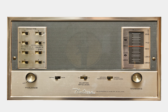
I have a 1960’s house that I purchased from the original owner. As a result I have the original Nutone intercom which is vacuum tube based and works really well considering it’s almost 50 years old. When I bought the house, the intercom didn’t work so I popped it off the wall and took a look at the tubes. You can’t tell if they are good or bad by looking at them but I wrote down the model numbers and went on eBay. I found all the tubes I needed for about $15 shipped. When they arrived I popped them in and it worked perfectly but being a 50 year old intercom, it only would receive AM radio. As nostalgic as that is, I like techno and electronic music. I noticed that the intercom had a switch that said radio or phono. I pulled the unit off the wall again and looked for the phono input and couldn’t find it. Finally I crouched down and looked up. There it was on the bottom of the unit. Since my stereo system is on the wall directly behind the intercom, I soldered in a nice piece of Canare coaxial cable with an RCA end on it and dropped it down the wall and put in a plate. Now with the switch set to phono, I hooked up to the tape recorder output on my stereo and have a CD player or airtunes pumped through the whole house. That’s how I’ve had it set up for the near four years I’ve lived here.
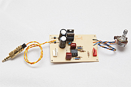
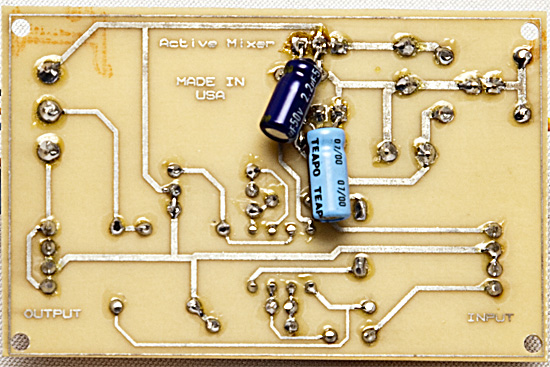
This has been great but from time to time I’ve noticed something missing out of the music so I tasked my friend James with building me a small two channel mixer that could fit inside the wall plate. He’s been on a roll lately of designing and cooking circuit boards for various projects and trying to perfect his techniques so I figured this would be a good, easy little project to hone some skills with. The board looks fabulous! It’s higher quality than many electronic devices I’ve opened up over the years even which is kind of scary really. It has a 78XX series regulator for the positive side of the op amp and a 79XX regulator for the negative side of an op amp. The gain is fixed but there is a potentiometer that adjusts the attenuation on the output side. It works on 12-18VAC. The PCB was made with the laser printer toner transfer method using glossy paper cut from catalogs that came in the mail and a cheap Scotch TL901 laminator.
He gave me the finished product and I hooked it up to test for a bit. When he had it and built it, he was testing with a 15vac wall wart so when I plugged in my 18VAC wall wart, it wasn’t being loaded down much (maybe 20mah) so there was really no typical voltage drop. That being said, it was putting almost 20 volts into the circuit and essentially running parts of the circuit at peak capacity. He suggested that I should use a lower voltage power supply. I stopped in at a local goodwill the other day and found a 12VAC 300mah wall wart for $1. That was one problem.
The other problem was apparent when listening to it because it was distorting the audio. I handed it back to James and he took the circuit home for troubleshooting. He found that the filter caps on the output side were slightly undersized. This was causing the negative power regulator to oscillate.
He sent it back my way with larger filter caps and I plugged in my new power supply. Now it’s good to go and ready for installation.
If you like the content on this site, please support it by using this link to order from Amazon. You know you were going to go there and buy stuff anyhow so why not help me pay the hosting bill.


I just purchased a house with the exact same intercom system. When I first turned on the system it’s quite for a couple seconds and then it builds a high-pitched crackly feedback type noise. I’ve determined myself to fix the unit and keep it as nostalgic as possible. Last night I found the phono connection and hooked my iPod to it. If the iPod is playing music before I turn on the intercom system the music will broadcast throughout the system and remote speakers without an issue. The second I turn off the iPod the feedback will start squealing again.
I when I started this journey I simply assumed the vacuum tubes were just dead, but maybe that’s not the case an there is a different issue causing this problem. Anyone have any bright ideas before I go searching for new tubes?
You should grab a set of new tubes anyways. If you don’t need them now, you’ll need them later. These intercoms don’t have an isolation transformer in them if I recall and they are very susceptible to sources of noise in your home. I have a dimmer for instance that I can hear through the intercom any time it’s on. Look around the house, turn things off. See if anything effects it.
The crackle makes me think it’s probably a bad tube though. I’d grab a set for troubleshooting.
Great to see you’ve got these old units up and running. With any old electronics, especially those that are from the mid 60’s and earlier, I HIGHLY recommend that the old capacitors (and possibly some of the resistors) be replaced. Tubes can last in storage in storage for many decades, caps won’t. I say that because the next time you “fire up” your intercom, that phrase could take on an unfortunate literal meaning. You, or your restoration technician, will need to pick up a Sam’s Photofact (a comprehensive list of wiring diagrams, schematics, parts lists, and so on) for your specific model.
I checked all the caps when I first got it working about 7 years ago now. They were amazingly all in spec. I haven’t really used it in a while now though so things may have drifted a bit. Maybe I’ll check them again if I’m bored at some point.