Latest Entries »


IMG_4715

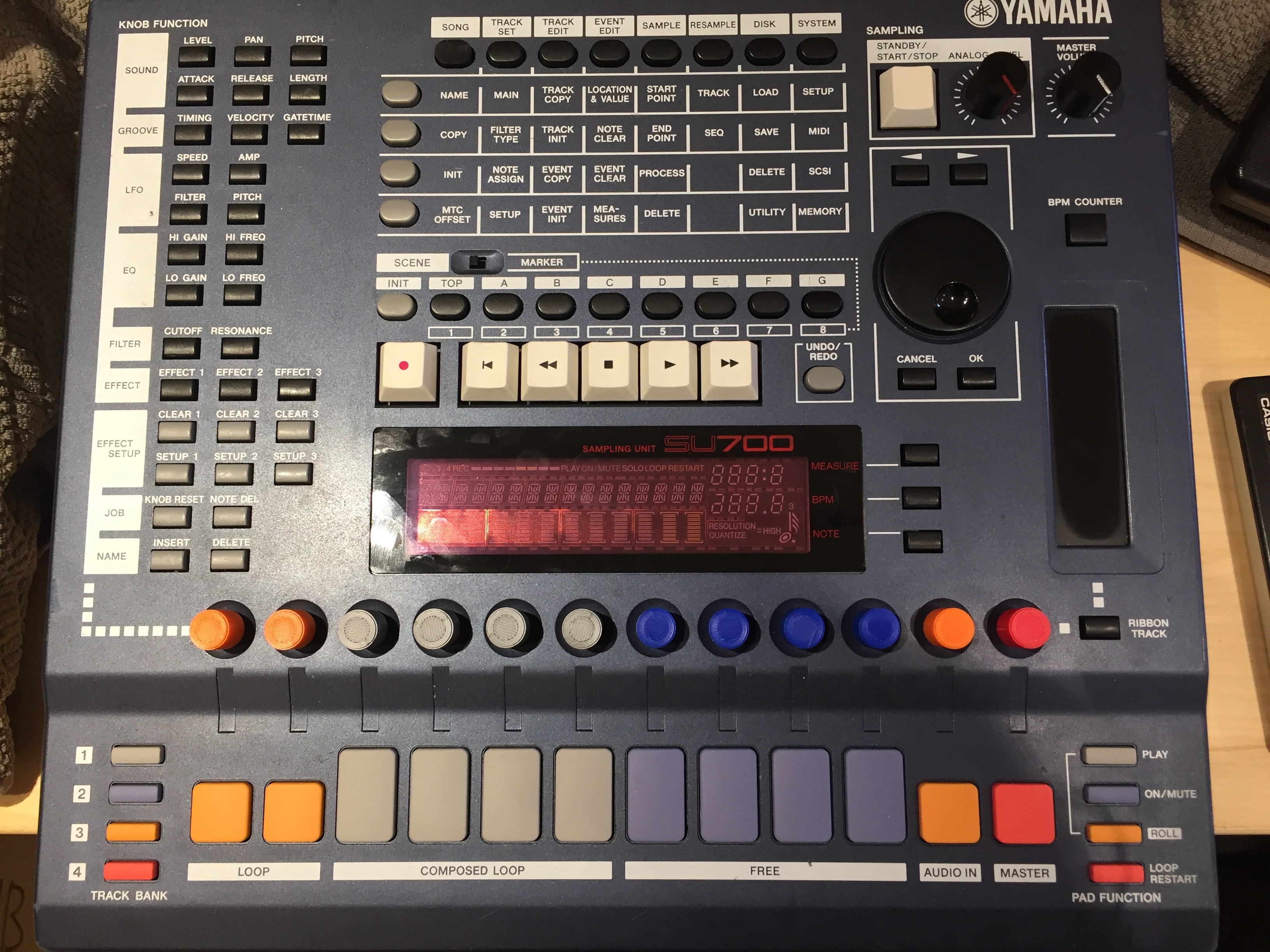
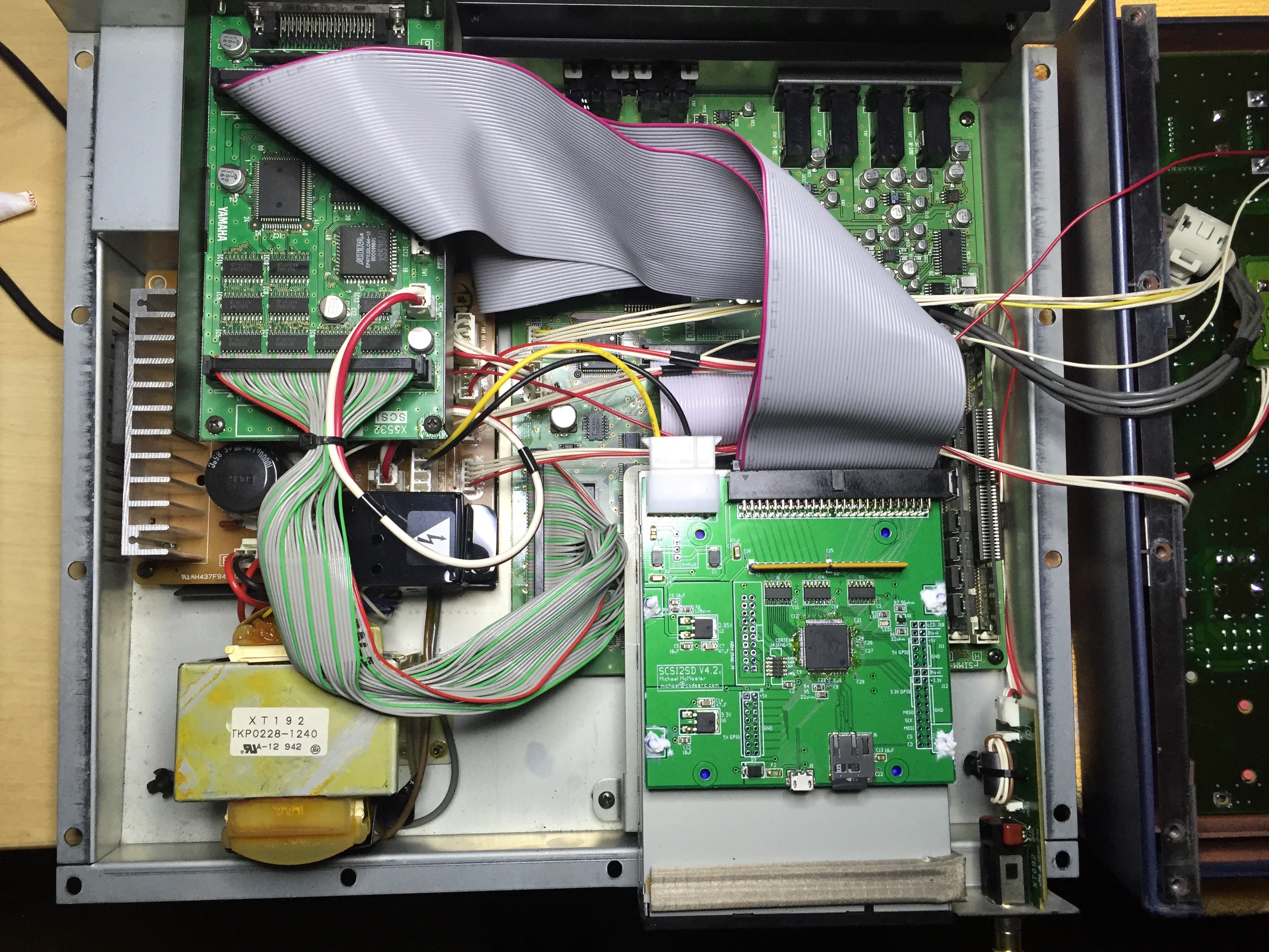
I have been hammering away on my Yamaha SU700 for almost a year now.  It is absolutely one of the most unique and interesting samplers I’ve ever used.  It’s in my top 5 hardware samplers of all time for sure.  This sampler is not without limitations…  No grid programming for instance.  That ok though, I have about 10 other samplers that will do that job just fine.  This one is good at it’s own thing though.  That thing is loops.

This is the best loop machine out there.  Yes, I tried the Octatrack.  I’m sure it’s way more powerful.  I don’t care though, it’s not even close to being as easy to use as this Yamaha.  The only other thing I suspect might come close is the Pioneer Toraiz.  I’ve tried that one in the store and I plan to purchase one at some point but the Yamaha will most likely still have something to offer even after that happens.

I wanted to share my workflow for capturing loops on the SU700.  This might sound complicated but it’s really not.  All you need is a calculator.  I’ll try to make my explanation as easy as possible.  It ONLY works if you know the exact BPM of the loop you are sampling.  This is intended for sampling loops you have created on other machines or perhaps loops you have purchased.  Here is my process:

  1. Sample your loop to one of the orange loop pads.  Hit the “start sampling” button on the SU first, then hit play on your sample.
  2. Stop sampling after the last of your loop is captured.  You don’t have to be precise here.
  3. Enter the sample -> process menu and trim will pop up.  Hit ok and trim the sample.
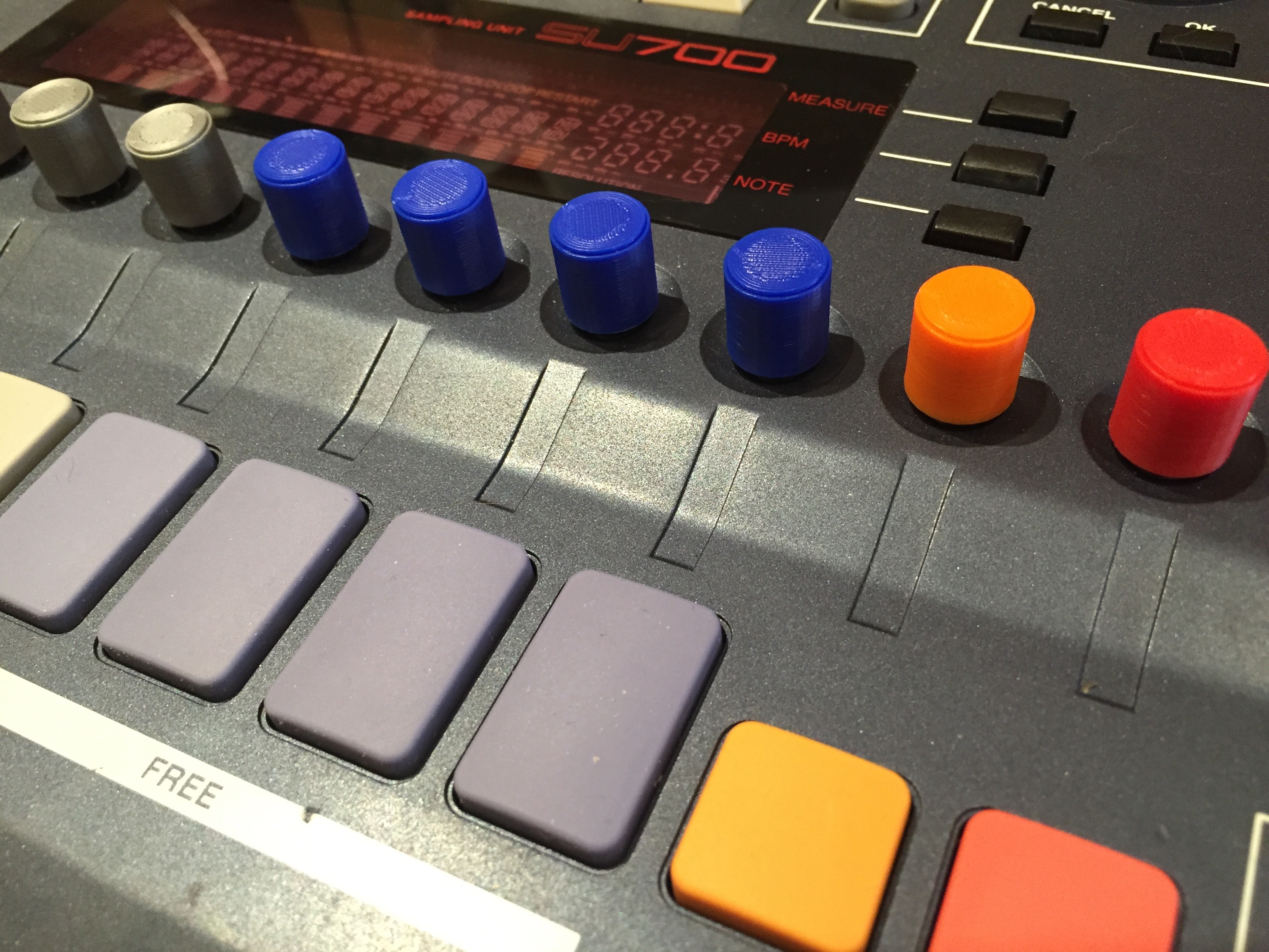
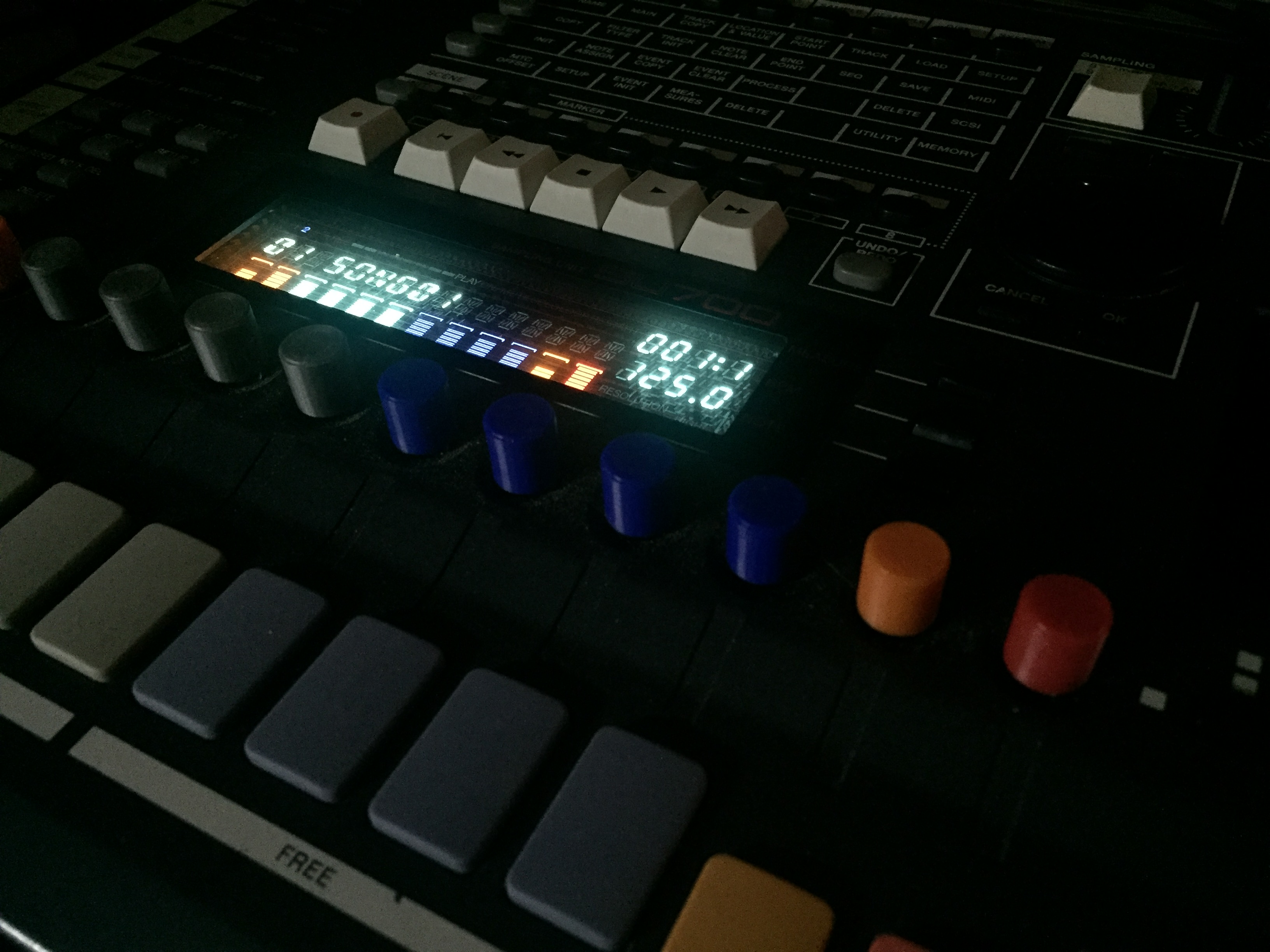
  4. Enter the track set-> setup menu.  Select “loop length”.  Set the measures and punch the BPM shown there into your calculator.
  5. Hit the division button on your calculator and enter the actual known BPM of the loop, then hit equals on the calculator.
  6. Go to sample -> end point in the menu matrix.  Hit the multiply button on your calculator and multiply the number shown as your end point.
  7. Hit equals and change the end point to that new number.  [hint: you might not be able to set it to the exact number, just get as close as you can]
  8. [optional] Change your SU700 BPM to the known BPM of your loop
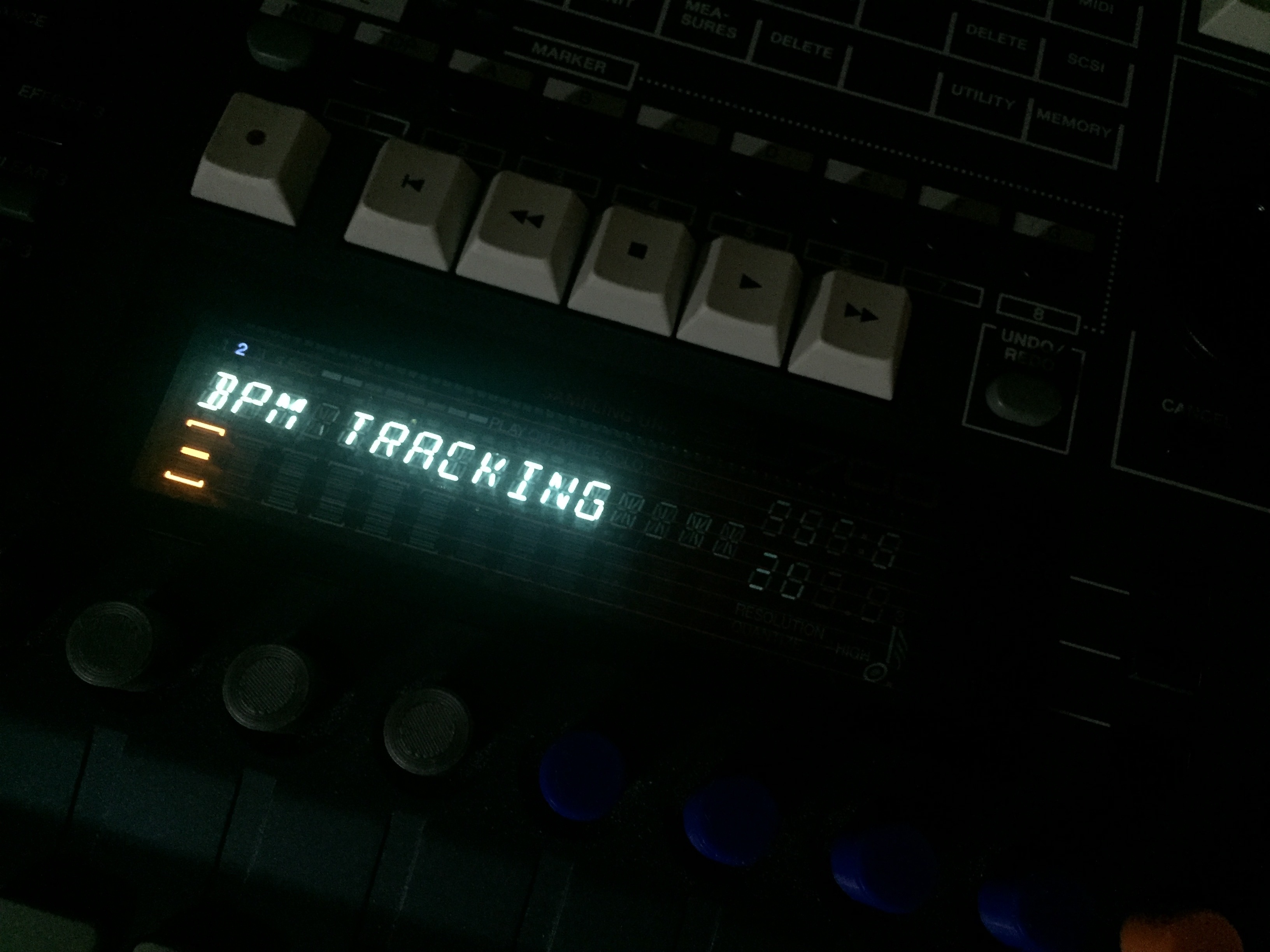
  9. [optional] Got to track set -> setup -> BPM Tracking and change from “SLICE” to “CHNG PITCH” this will prevent choppiness
  10. Hit play on the SU and it should sound absolutely precise and spot on.

IMG_4714

I know that probably looks weird so let me just show the math here with some example numbers:

Let’s say you have a 115 BPM loop…  You sample it, and trim it.  When you go to “loop length” it shows “108.2”.  On your calculator do this:

108.1 / 115 = 0.94

Now go to the end point and you see that it’s currently 389956.  Do this on your calculator:

0.94 * 389956 = 366558

Now you need to change the end point to 366558 and you are basically done.  You have an absolutely perfectly trimmed loop on your hands.  The entire process takes me about 20 seconds?  Much quicker than doing it by ear.  I recommend the 2 optional steps.  Usually I do those things to start with and then play around with this settings later if I want a different effect.

This process may even apply to other samplers.  If it does, that means you have another good loop machine in your hands and I want to know about it.  Please leave a comment.  I hope someone out there still loves this sampler as much as I do and finds this useful.

IMG_4716

Yamaha SU700 Sampler Restoration

IMG_3836I had a SU700 briefly a couple of years ago but I sold it off because I didn’t really understand the workflow.  It had been described to me as a hardware version of Acid but that description is not particularly accurate.  I’ve been on a music kick lately though and came across this sampler again in my research.  I decided to buy another one and give it another shot.

I found this particular SU700 on eBay for $50.  It was in pretty bad shape.  All of the knobs were missing and most of the encoders were shot. Someone had long since given up on this poor sampler.  It was sold to a pawn shop, then I think they sold it and it was likely brought back to them because it was defective.  I’m still curious when the knobs disappeared though.

Finding new drop in replacement encoders is difficult and expensive so I researched for some alternatives.  I ran across this page http://www.albates.com/yamaha-su700-encoder-repair-and-replacement/. He lists 3 recommended alternatives.  I ended up going with the EC12E24404A8.  I had to bend the leads straight out and wire up small jumper wires on each encoder to make it work but I’ve been very pleased with the result.

IMG_3806

Next, now that it was working again, it was time for some new knobs.  They were all missing.  At first I printed some generic black knobs I found on thingiverse but they fit kind of loose for my taste and they weren’t quite what I was looking for.  I ended up designing my own from scratch.  What you see in the pictures is the 7th revision on the small knobs and the 2nd revision on the larger knobs on the two volume controls.

Here’s a link to the small SU700 knobs https://www.thingiverse.com/thing:1626229

IMG_3837

Here’s a link to the larger volume knobs https://www.thingiverse.com/thing:1627286

IMG_3838

Aside from the knobs, there was one of the matrix button covers missing.  Someone on eBay is selling one for $9 +$7 shipping.  This seemed a bit steep to me so I designed my own.  It three revisions to get it right.  It’s not rounded on top like the stock ones but it does the same job and looks close enough for me.

Here’s a link to the matrix button cap https://www.thingiverse.com/thing:1627287

IMG_3839

Finally, it was time for a SCSI board.  The floppies work fine but in the end swapping 5-6 floppies for a song is tedious.  SCSI boards are uncommonly found on eBay and they are usually $150.  I found an A3000 sampler on Shopgoodwill and managed to get it for $95.  All A3000’s (unless it’s already been pilfered) have the exact SCSI board that is required for the SU700.  I pulled it out and then put the sampler on eBay for $100.

I did not want an external SCSI drive that would be loud, large, and require a separate power supply so I ended up building an SD2SCSI card for it.  I was very pleased when I was first able to format the card.  I put 2 partitions of 1gb each on a 4gb microSD card.  Even one of these partitions should last for ages.

IMG_3824

MA-309The MA-309 is the same as the MA-216 without the SC-01a speech chip and support circuitry installed. It was used in the System80 pinball machines Super Orbit, Royal Flush Deluxe, Amazon Hunt, Haunted House, Spirit, Krull, Goin’Nuts and video game Mad Planets. It will also work with ROMs from Mars, Volcano, Black Hole, Devil’s Dare, Rocky, Striker, Q*Bert’s Quest, Caveman and video games Reactor, Qbert, Krull, Three Stooges  although the speech feature from this game will obviously not work. If someone implements the SC-01a in HDL then adding the support logic is trivial.

This code works as-is on the cheap Alterra Cyclone II dev boards available on eBay for $20 or so.  Hook up a PS/2 keyboard to it and you can trigger the sounds with it.  Disable/remove the PS/2 code and this should plug straight in to one of the real machines listed above.

https://github.com/FPGA-Code/Gottlieb-MA-309


MA-55

The MA-55 was used in Panthera, Spiderman, Circus, CounterForce, StarRace, James Bond 007, Time Line, Force II, Pink Panther, and the export versions of Volcano, Black Hole, Devil’s Dare, and Eclipse.

This code works as-is on the cheap Alterra Cyclone II dev boards available on eBay for $20 or so.  Hook up a PS/2 keyboard to it and you can trigger the sounds with it.  Disable/remove the PS/2 code and this should plug straight in to one of the real machines listed above.

https://github.com/FPGA-Code/Gottlieb-MA-55


Gottlieb MA-490 Pinball Sound Board in an FPGA

Screen Shot 2015-12-14 at 10.04.56 AM

The Gottlieb MA-490 is a cost-reduced board which is just the older MA-55 with a kludge piggyback board plugged into it increasing the ROM capacity. Used in Amazon Hunt (late production), Rack’Em Up, Ready… Aim… Fire!, Jacks to Open, Touchdown, Alien Star, The Games, El Dorado City of Gold and Ice Fever.

This board is meant to be loaded onto an Alterra Cyclone II board and hooked up to a PS/2 keyboard to be triggered.  It has not been tested in a real machine but should work with a couple of simple modifications.

https://github.com/FPGA-Code/Gottlieb-MA-490


William System 3 sound board

Here’s the sound board used in Williams System 3 and System 4 pins from the late 70s to early 80s. It’s simpler than the System 6/7 board but similar architecture, 6802 CPU(similar to 6800) with 128 bytes of RAM, 2K ROM and a 6820 PIA driving a DAC. Curiously the ROMs for every game using this board seem to be identical so it seems they used the same sounds in all of the pins of this era.  Maybe this shouldn’t be surprising since it’s right on the tail of the electromechanical chime era.

The top level file is set up for an Altera Cyclone II mini development board available on eBay for less than $20.  There is a PS/2 interface to control the sounds which can easily be removed if you are going to attempt to use it in a real machine.  This has not been tested in a real machine yet.

Here is the code, it’s a little messy but it will be cleaned up eventually if time permits:

https://github.com/FPGA-Code/Sys4-snd


Bally AS-2518-51 sound board in an FPGA

Screen Shot 2015-12-04 at 11.23.32 AM

This is a Bally AS-2518-51 sound board, the predecessor of the Squawk & Talk implemented in an FPGA.  This is set up with the ROM for the 1978 pinball Nitro Ground Shaker but other ROMs are available. http://ipdb.org/showpic.pl?id=1682&picno=37007

Some general info about the hardware http://zerocharactersleft.blogspot.com/2014/07/retro-pinball-reverse-engineering-bally.html
This one is interesting because it uses a AY-3-8910 sound synthesis chip to generate all the sounds rather than driving a DAC directly from the PIA. It’s got a bit of a different sound as a result.

It has not been tested in an actual pinball.  Currently it is set up to plug in a PS/2 Keyboard that will allow you to trigger all of the sounds.  Some keys are repeats, others are blank, it was just a quick hack.  The PS/2 hack is in the top level file and easy to remove which would theoretically allow you to wire this up in a real pinball.

The target board for this is the very economical Altera Cyclone II dev board.  They are all over eBay for less than $20.

Here is the code:

https://github.com/FPGA-Code/AS-2518-51_snd


Tenergy Li-ion 4400mAh Roomba 400 Battery Review

IMG_2635

Several people over the years have found my blog posting on why not to use Lithium battery packs in Roombas.  Some people have taken the information at face value, others have argued with me in the comments and tried to claim my views on the subject are not valid.

Some of the folks over at Tenergy also noticed my article and decided to send me a battery to prove to me they have resolved the issues I was citing.  Here is a link to the battery in question:

http://www.all-battery.com/lithium_roomba_400battery-34083.aspx

In the interest of full disclosure, in consideration for the battery, they only asked for my honest review along with a link back to the product to allow people to find it.

IMG_2637

At this point in time, I have been using the battery lightly for about a month.  I use my roombas somewhat sporadically.  This may actually shorten their life due to lack of cycles and a poor factory charger circuit.  So far, this pack seems to be holding up just fine.  One thing I should point out that is different about this pack from the other lithium packs I used in the past…  When the other packs ran low, the Roomba light would start to glow orange and then suddenly the roomba would die in place.  In other words, it never had enough charge left to bring itself back to the base.  The batteries low volt protection cutout would kick in and save the cells from damage.

This pack appears to work like a typical NiMH pack.  The light eventually goes red like it should and the robot stops moving but the power remains on.

As far as runtime, I’m using the pack on hard surfaces.  I haven’t paid close attention but it seems to go for a couple of hours.  One day I will time it and update the review, for now though, I wanted to post my initial thoughts.

Similarly, I will obviously need to reserve my judgement on longevity until the pack starts to noticeably deteriorate.  That could be months or could take over a year.

So far, if I had to pick one complaint about the pack, I would say that one of the retainer clips is unable to snap into place.  This is a pretty minor issue that I could probably fix with some sandpaper or a knife but I shouldn’t have to.  I’ve cleaned the area under the battery and pushed on it pretty hard but it just won’t snap in there for some reason.

IMG_2811

For now, I will say that the price is currently $68.99.  This is marked down from the typical $90.  The Tenergy packs for the 400 are $25 on Amazon.  So what do you get for 3x the price?  I’m not sure yet.  Only time will really tell there.  The pack is certainly lighter than a NiMH pack so it’s putting a little less wear on the robot.  It seems to last similarly to some of the best NiMH packs I’ve had.  It’s not exactly an all-day battery pack however.  In the coming months, I’ll try to monitor the health of this pack a bit more closely and possibly more scientifically.

My first lithium pack for the Roomba was $150.  When it prematurely cooked, I was not pleased.  At $69, if I got a year out of this one, I probably wouldn’t complain too much but then again, if it only lasts a year, why pay any premium on it at all?  Let’s hope that I’m able to favorably speak of this pack for years to come as “the best Roomba battery I’ve ever had”.

Dead Hypex SMPS600 V3 Power Supplies

SMPS600

A couple of years ago I decided to build myself some class-d amps based on the Hypex NC400 modules.  I had also designed some custom billet aluminum cases but I knew they were going to take a while so I put them in temporary enclosures.  I had noticed during the summer months when the weather was warmer, one channel would click off.  I finally figured out it was thermal shutdown and so I turned the case over and put some metal objects on top to act as heat sinks.

Fast forward to a couple weeks ago, I needed to turn my equipment off to make some changes to the setup.  It took me overnight to make all of the changes and when I went to plug the amps in the next day, neither would turn on.  No signs of life at all.  No clicks, no lights, nothing.  I was a little confused that both could die at the same time.  They are in separate cases on opposite sides of the room but when I popped them open, I reached for my cap wizard and started testing out some of the caps in the power supply.  Turned out several were cooked.  Some did not even move the needle on the cap wizard.  To my suprise, even one of the largest caps, a 820uf @ 200v, had drifted far out of spec.

I decided I would just replace all of the caps on the power supply boards because I wanted to make sure they were perfectly matched and I figured they all probably have a shortened life span from the heat they incurred.  My first task was to remove and map out all of the caps.  To get to the 2 largest caps on the board, the large heatsink HS1 needed to be removed.  In order to remove that large heat sink, R2 needed to first be removed to access the screw holding D43 to the heat sink.  After I got that out of the way, then I could  remove and catalog the caps.  This board is not particularly easy to work with.  The holes are drilled with very small tolerances compared to most.  This means you really need to get all of the solder out of the holes or the new components won’t go in easily.

4x 820uf 200v (C1, C15) http://www.digikey.com/product-detail/en/LGW2D821MELB30/493-8519-ND/1966875
16x 220uf 35v (C3, C4, C5, C6, C7, C8, C13, C14) http://www.digikey.com/product-search/en?vendor=0&keywords=35ZLS220MEFC8X11.5
4x 22uf 63v (C22,C26) http://www.digikey.com/product-search/en?KeyWords=63YXJ22M5X11&WT.z_header=search_go
2x 470uf 50v (C9) http://www.digikey.com/product-detail/en/UHW1H471MPD/493-6972-ND/3664388
12x 100uf 100v (C10, C11, C12, C19, C20, C21) http://www.digikey.com/product-detail/en/100YXJ100M10X20/1189-2149-ND/3563802

After that, I ordered the caps for about $40 shipped and replaced them when they showed up.  So far so good.  Everything seems to be working again.  Lesson learned.  Even though these amps use a very small amount of power and run very cool for their power outputs, cooling is still super important.  I would suggest having plenty of cross-ventilation in your cases.  Make sure you leave adequate distance between the amp and power supply.  Also make sure your NC400 module is attached to a larger and thicker piece of metal to properly cool it.  Apparently a smallish piece of light gauge aluminum is not adequate when in an enclosed space.  If you need to replace your caps, ONLY use 105 degree varieties and use the ones rated for the most amount of hours at that temperature.

NC400 & SMPS600

Sharp Image SI-727R-DS Repair Log

This monitor has been on my desk for months because I’ve been avoiding it but I’ve decided that it’s taking up too much space so I’ve decided to start digging into it again.  I’m going to document my repairs here in hopes that it will help someone else out to see my troubleshooting process.

The symptom of the issue is no picture.

The problems are several.  The monitor is switchable between standard and medium resolution hence the “DS” in the model name which stands for dual sync.  When I attempt to run it at 15k, things seems somewhat stable.  There is no picture but when I test B+, it will sit there right around 130v which seems pretty reasonable.  Testing with the high voltage probe I get about 130v on the anode which tells me something in the flyback/HOT area is not working correctly but I don’t have a schematic so I’m flying blind on it.  When I hit the base on the oscilloscope, I get a reasonably nice looking square wave that seems to be at the correct frequency and looks happy.

Oscilliscope reading (base)

So that makes it appear that the driving waveform is ok.  When I hit the collector, I get this:

Oscilliscope reading (collector)

That does not look good.  Theoretically I should be getting voltage spikes that go well of the screen when the HOT grounds the flyback.  The scope is set for 50 volts per div and I’m barely covering two of them so something is clearly wrong here.

When I switch over to medium resolution (25k jumper) things get much worse.  The B+ pops on and starts at about 140v, then it keeps climbing and the monitor starts getting noisy to the point where I’m concerned and then I shut it down.

I’ve tested the flyback with a ring tester and it looks good but perhaps there is a different problem with the flyback that cannot be diagnosed with that tool.  I know for sure the HOT is good, I have several of them and they all test the same.  When I pull the HOT out of circuit, both the 15k and 25k mode act the same and give the same B+ voltage of roughly 130v.  The only difference is the waveform reading on the base of the HOT.

Powered by WordPress. Theme: Motion by 85ideas.