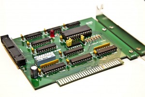
My final assembled XT-IDE 8-bit ISA card
Once I started messing with my IBM PC XT, I realized that there were things I had taken for granted all along since my first PC compatible system was a 386. I didn’t realize that IDE uses a 16-bit bus and it would take some trickery to use an IDE device in an older 8-bit system like the XT. I searched around and found that there were in fact 8-bit ISA controllers but they were expensive and rare. Finding one these days would be a stroke of luck or a dent in the pocket book. I was about to design my own when I came across the XT-IDE project. The XT-IDE project is an open source venture where a group of people designed exactly what I needed with fairly common off-the-shelf parts. I had my friend James to burn the code onto the eeprom for me because I have no way to put something on a 360K floppy disc but aside from that, the project primarily consists of easy through-hole soldering.

Front side of the unpopulated XT-IDE PCB
I ordered my board the other day from Andrew Lynch who can be found lurking in this huge forum thread. It was $14 including shipping which I felt was more than fair considering the quality of the board. It’s a very professional dual-sided PCB with a full solder mask and silkscreen. It would take me far too much time to attempt to replicate this at home. It’s also nice that it has all of the settings printed VERY clearly on the board and the url for www.vintage-computer.com so I won’t forget where I found this project.
The bill of materials looks a little daunting at first but it’s really not a huge project. The list below references Jameco part numbers. There are a few non-critical items and some others that you can pillage from other ISA cards such as an L-bracket, pan screws and shorting blocks (jumpers). I’m personally going to skip using most of the sockets since I’m fairly confident with my soldering skills and dual-wipe sockets tend to add another point of failure.
1               XT-IDE PCB (get this from Andrew lynch)
10   25523 	CAP,MONO,.1uF,50V,20%
1    1945428 	CAP,RADIAL,47uF,35V
2    45129 	IC,74HCT688
1    46316 	IC,74LS04
1    46607 	IC,74LS138
1    47466 	IC,74LS32
1    287144 	IC,74F245,DIP-20
3    282642 	IC,74F573,DIP-20
1    74827     	Atmel EEPROM IC, 28C64
2    112214 	SOCKET,IC,14PIN,DUAL WIPE
6    112248 	SOCKET,IC,DUAL WIPE,20PIN
1    112272 	SOCKET,IC,DUAL WIPE,28PIN
1    526205 	SOCKET,IC,16 PIN,390261-4
3    112432 	SOCKET,SHORTNG BLKS,RED,CLSE
1    690662 	RES,CF,150 OHM,1/4 WATT,5%
6    691104 	RES,CF,10K OHM,1/4 WATT,5%
2    857080 	MOLDED SIP,9PIN,BUSSED,10K,2%
1    333949 	LED,GREEN,572NM,T-1 3/4
1    1939562 	SWITCH,DIP,SPST,8-POS,16-PIN
1    53604 	HEADER,RT MALE,2RW,40 CONT
1    109568 	HEADER,.1 ST MALE,2RW,16PIN
1    109576     HEADER,.1 ST MALE,1RW,3PIN
2    2094389 	SCREW,PAN HEAD,PPN4-40X1/4
1    N/A        Keystone 9202 ISA bracket with 2 PCB mounting tabs.
Once I had all of the parts together, it was time to check out the build instructions. This project is a VERY easy build. All of the IC’s are labeled on the PCB, all of the caps are identical except one which is labeled and called out and all of the resistors are the same aside from the one that goes with the LED. There are only two gotchas that I can think of. First off, before you solder in the 40 pin IDE connector, you should pull the key pin out from the connector. Grab an IDE cable and line it up with your connector, you will see which one is the key pin fairly quickly. Secondly, the default dip switch setting is correct on the back side of the PCB but incorrect in the build instructions. Set it to 01110111 as stated on the back of the card. If you need to set this to a different setting, you will need to re-flash the firmware on the eeprom for some reason. The default seems to work fine however so no big deal.
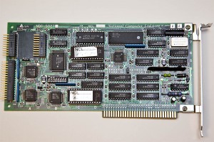
The original NCL MFM controller that came in my PC XT
Overall this project has cost me about $30. I’ve learned some new stuff and I can now use my IBM PC XT with a modern IDE hard drive. My next step will be to try to use the system with a compact flash card. Now I can install MS-DOS 6.22 and hopefully Xenix at some point without disrupting the original MS-DOS 3.2 file system.

