Latest Entries »

Adding a serial port to my Zipit part 1

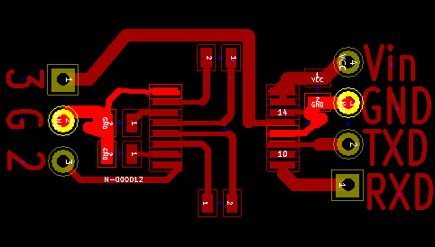
I’ve been fighting with Kicad to design a tiny little serial converter for my Zipit.  The Zipit needs a serial converter because the outputs inside the Zipit don’t conform to the RS-232 voltage standards and they are unbuffered.  In other words, most RS-232 devices probably wouldn’t recognize them as they sit AND you could inject a voltage spike directly into the CPU if you decided to hot plug a device.  These serial transceivers have some level of resilience built into them that will protect against such spikes.  Some of the information I’m using in this project is coming from this page:

http://zipit2system.sourceforge.net/?page_id=82

I’m going to use a different chip than he does however.  I priced out the chip he spec’d and it was around $8.  Not sure why, there is nothing particularly special about it.  I chose a different chip for my project though.  I’m going with the Maxim MAX3221CAE in a ssop16 package which is ridiculously small and costs less than $2.  There are sixteen pins on the chip and it is roughly 6.3mm long.  This will be perfect because I am going to install my serial board inside the Zipit entirely.  Then I will use a 2.5mm jack to a DB9 cable or something similar to actually hook up to other devices.  The board I’m making will mount inside the lid behind the LCD screen.  Believe it or not, there is plenty of room back there.  My goal will be to make it so that no grinding or cutting is necessary but somewhere along the way I’ll need to drill a hole for the actual port anyways so no big deal either way.  I’d like to keep it looking as stock as possible.

Here is the schematic I designed(with help from James):
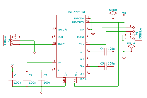
A flaw James pointed out with the other serial design is that the charge-pump capacitors were omitted.  This means that the output still may not have properly complied with the RS-232 spec with regard to voltage levels since those are part of the circuit that builds up the voltage.  I’m sure the other design works in most cases but it’s possible there are stubborn, older devices that could choke on it a bit.

Correction 6/25/2010: After looking at the datasheet for the Maxim 3223e, it appears to have internal charge-pump caps.  The chip is still much too large for my purposes but slightly easier to implement because it has fewer external components.

Anyhow, time to etch a board and see if it works.  Wish me luck.

TinyELF delay timer

Even this slow old architecture is actually still really quick.  You’ll often need to burn off some clock cycles between operations just so you can see the output.  Here is a little subroutine I wrote for the 1802 that is adjustable and can be shoehorned into code you may have already written.  You can hook it write into many of the early programs in Tom Pittman’s book “A Short Course in Programming“.  Pretty much anything that has you pushing the “I” key for it to move forward.

0020    F81F    LDI The second byte determines the delay amount

0022    B4        PHI R4 Puts the delay counter into R4

0023    32XX   BZ XX Branch if D=0, second byte directs back.

0025    94        GHI R4 Puts the counter from R4 into D for comparison

0026    24        DEC R4 Decrements R4 by one

0027    3020   BR XX Branches back to check if D is zero.

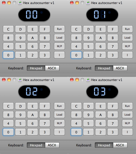
Here is an example where I have hooked the delay back into my hex counter program so that you don’t have to push “I” for the counter to increment.  I have left the old code structure in tact so you can see the differences.  I also changed the counter location in memory to 0030 but this is arbitrary.

TinyELF Hex autocounter

0000   6400  OUT 4    clear hex display
0002   90       GHI R0  zero the accumulator
0003   B2       PHI R2   Set hi byte to zero
0004   B3       PHI R3   Set hi byte to zero
0005   A3       PLO R3  Set lo byte to zero
0006   F830  LDI         Set D to 30
0008   A2      PLO R2  Set R2 to 30
0009 52         STR Clear 0030 byte
000A   E2      SEX R2  Set X to R2
000B   3020 BR           Instead of waiting for “I”, branch to delay
000D   13       INC R3  Count up
000E   83      GLO R3  Set D to the current count
000F   52       STR R2   Store counter value in 0030
0010   64        OUT 4     Put contents of 0030 on display
0011   22        DEC R2  Keep X pointing at 0030
0012   C4C4   NOP        No need to wait for “i” to be lifted now
0014   300B   BR           Loop back to where wait for “I” was

timer routine;
0020   F85F LDI         The second byte determines the delay amount
0022   B4      PHI R4  Puts the delay counter into R4
0023   320D BZ          Branch when D=0 back to AFTER the branch to 0020
0024   94      GHI R4  Puts the counter from R4 into D for comparison
0025   24      DEC R4  Decrements R4 by one
0027   3023 BR           Branches back to check if D is zero.

USB Flash drive fail

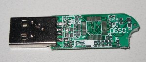
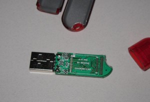
So a guy I know finds this usb stick at his place of work.  It has no markings at all, no size, brand or anything.  It was sitting on the side of someone’s desk because it wasn’t recognizing so it got set aside.  He gave it to my friend who cracked it open to see what was inside of it:

Um… anyone else notice something missing?  Buyer beware of the generic, unmarked USB memory stick.  When you can get a HP 8 GB USB Flash Drive for $16.99, why would you even bother with this crap anyways?

How to use MD5 checksums on Mac OS X

Have you ever wondered what to do with that obscure long number that is sometimes seen posted with files that you download?  If you have ANY suspicion on whether a file is legitimate or not, you should use that number to make sure you are getting the file from the correct source.  Other than checking for trojan’d files and other dirty deeds you can also check to make sure you downloaded the WHOLE file.  Why waste a DVD by burning a corrupted ISO?  It’s easy enough to run the checksum so that you don’t have to guess if the file is good or not.  Open up a terminal and type:

md5 filename

See?  It’s dead simple.  Just make sure the number matches the one that is posted on the trusted site where you downloaded the file.  If you want to get really fancy with the process, there is an automator script available from apple called MD5 Checksum 1.0 that allows you to right click and check any file right in the finder.

TinyELF Hex Counter

I’ve been trying to figure out how to do this nearly since the beginning.  This program represents a huge milestone for me.  It’s the first program that I have created from scratch that does something sort of useful.

It’s amazing how much debugging can go into something so simple as a hex counter.  At first I had to press “I” three times for the counter to start moving upward.  Turns out I had a few commands out of order.  Also, I had a bug where the counter location in memory would not have been properly reset to zero if R2 didn’t have a residual value in it.  Then I had some other misplaced bytes that were confusing me a bit.  I think I have all the kinks worked out now so I’d like to present my hex counter:

0000     6400    OUT    4        clear hex display
0002     90         GHI     R0    zero the accumulator
0003     B2         PHI    R2      Set hi byte to zero
0004     B3         PHI    R3      Set hi byte to zero
0005     A3         PLO    R3     Set lo byte to zero
0006     F820    LDI                Set D to 20
0008     A2        PLO    R2      Set R2 to 20    
0009     52        STR           Clear 0020 byte
000A     E2        SEX    R2      Set X to R2
000B     3F0B   BN4               Wait for “I” to be pushed
000D     13         INC    R3      Count up
000E     83        GLO    R3      Set D to the current count
000F     52         STR    R2      Store counter value in 0020
0010      64        OUT    4         Put contents of 0020 on display
0011      22         DEC  R2        Keep X pointing at 0020
0012     3712     B4                   Wait for “I” to be lifted
0014     300B    BR                  Loop back to wait for “I”

Please excuse the formatting, it’s late.  Anyhow, the program sets itself up by clearing the display, zeroing R3, setting R2 to 20, clearing the byte at memory location 20 and of course setting X to R2.  R2 does double duty in this program.  It points X at byte 0020 in memory and it also tells the STR instruction where to store the value of D.

After the initial setup, we jump into the loop.  First we increment R3(the counter).  Next we stick the counter value in D so we can then store D at memory location 0020.  Then we display the value of 0020 since that is where R2 is pointing.  The 64 OUT 4 instruction incremented the value in R2 so we decrement it immediately so R2 still points at the correct location and doesn’t leak memory.  If you want a good demo of a memory leak, change the value of 0011 from 22 to C4 and then run the program.

I know this program isn’t rocket science but give me a break, I’m still in chapter 4.  Looks like I still have a LONG ways to go to program in “hello world” even…

Sewell Minideck SW-22857 review for MacBook Pro

I’ve owned a Mac now since late 2008.  Soon after I bought it, I discovered how cool multi-monitor support is.  Oddly, this discovery didn’t quench more thirst for more screen real estate, it simply made me want more and more.  On my MacBook Pro, there is only one monitor output.  I would have assumed that was that and there would be no way to add more screens but then I found the Sewell Minideck SW-22857.

This ingenious device allows you to hook up to 5 extra monitors to a computer even as underpowered as a Atom-based netbook.  That is a testament to the fact that it doesn’t consume a lot of overhead.  On my system which is a 2.53GHz dual core, it seems to only take 1.2-2.2% of one of the CPU’s at idle and it spikes to 2.6% when I’m pushing it with window scrolling, etc. Works for me.

Now personally I would have assumed that a USB-based graphics card would be kind of a gimmick.  Surprisingly enough though, I think this adapter will work well enough to be useful.  I did try full motion video on it and it sucks.  Totally useless and choppy.  I would estimate I’m getting 15-20fps on it.  To me, this is pretty much unacceptable, YMMV.

I did a lot of research before I bought this device.  One thing surprised me.  It’s smaller than it looks in the picture.  Probably half the size of a standard external 2.5″ drive but a touch thicker.  Another thing worth mentioning is that you should just go to the website to get the latest driver.  From my understanding, the bundled one doesn’t work too well.

Supposedly this is one of the only USB-VGA/DVI/HDMI adapters that actually works properly with the Mac.  I’d believe that.  The bummer is that they know it and charge dearly for it.  I tried and tried to wait them out but the price never dropped.  I could not find this device ANYWHERE legitimately cheaper than $100.

The only problem I could find with the whole setup is that my monitor does not seem to properly sleep with this adapter.  The screen goes black but the back light stays on.  If I figure out what is going on with this, I’ll post an update.

Update 6/30/2010 – Still haven’t figured out the sleep mode on the screen but I have found that you cannot take a screenshot of anything running on USB-connected screen under Mac OS X

A closer look at the 64 (OUT 4) instruction

In Tom Pittman’s book, “A Short Course in Programming“, he introduced the 64 OUT4 instruction in chapter 3 with little explanation other than saying that OUT 4 would output the next byte in memory to the hex display.  This is fine and dandy of course but only if P=X.  I glossed over the P=X part the first time I read chapter 3 however so when he re-introduced OUT 4 in chapter 4, I found myself a bit confused.  In program 4.2, he tries to make sense of this concept.  I am going to take the liberty of recommenting the code to try to make even more sense of it and drive this concept home:

0000 90		GHI 0	.. set D=R0(hi byte), R0=0 after the computer resets
0001 B8		PHI 8      set high byte of R8 to value of D which is zero
0002 80		GLO 0      set D=R0(lo byte), this could JUST as easily be 90
0003 A8		PLO 8      set low byte of R8 to value of D (again, zero)
0004 3F04 WOW:	BN4 *	.. WAIT FOR "I" (This is a good description)
0006 E8		SEX 8      set X register to point at R8
0007 64		OUT 4	.. OUTPUT TO DISPLAY (see more down below)
0008 C4		NOP	.. this byte gets ran so it is critical
0009 3709	B4 *       wait for you to take your finger off "I"
000B 3004	BR WOW	.. REPEAT (start at the wait for "I" statement)

This program as written sends every byte in memory out to the hex display starting at location 0003 in memory.  If you want to start at the beginning of the memory, change 0002 to 90.  This will make sure that R8 is completely zero’d out when you start your count.  One more observation I have is that location 0008 DOES get executed.  If you want to make a slightly more confusing program but save a byte of memory, you can omit the c4 instruction at the location.  Just make sure you change the next branch command to 3708 so it jumps to the correct location.  You can FURTHER save another byte of memory if you omit the 80 GLO command.  Once you’ve GHI’d, you have your D(accumulator) set to zero so why not just PHI and PLO after that without GLOing?

Now for the big explanation.  Obviously the meat of the program happens when X gets pointed at R8.  That tells the OUT4 instruction to output whatever memory location that R8 is pointing at to the hex display.  Usually OUT4 looks at R0 for it’s next byte to display.  It also increments whichever register it’s looking at.  This is why the next byte after 64 usually is skipped and not executed.  Hopefully this makes perfect sense to you by now.  Also, there is nothing special about R8.  Tom just arbitrarily chose R8 out of the stack.  Here is my modified version of Program 4.2 that is smaller, starts at an earlier memory location and uses R2 as the display byte pointer(if that is the proper term…):

0000 90		GHI 0	.. set D=R0(hi byte), R0=0 after the computer resets
0001 B2		PHI 8      set high byte of R2 to value of D which is zero
0002 A2		PLO 8      set low byte of R2 to value of D (again, zero)
0003 3F03 WOW:	BN4 *	.. WAIT FOR "I" (This is a good description)
0005 E2		SEX 8      set X register to point at R2
0006 64		OUT 4	.. display contents of memory location pointed to by X
0007 3707	B4 *       wait for you to take your finger off "I"
000B 3003	BR WOW	.. REPEAT (start at the wait for "I" statement)

PLOing and GLOing with the TinyELF

In trying to understand the PLO (put low bit in D) and the GLO (get low bit from D) commands, I’m going to write a program that cycles through R1-RF and increments the registers one at a time.  This program is pretty darned boring unless you have the memory contents in full view on the emulator.  Let’s get started:

0000      90      GLO         Set D to zero

0001       A1      PLO         Set R1 to zero

0002      11       INC          Increment R1 (This is the start of where we loop it)

0003      91      GLO         Set D to value of R1

0004      A2     PLO         Set R2 to value of D

0005      92     GLO         Set D to value of R2

0006      A3     PLO         Set R3 to value of D

0007      93     GLO         Set D to value of R3

……      and so on and so on until  …….

0020     30      BR            Unconditional branch to the next byte

0021      02                       Start the program again from 0002

I would suggest running this program in step mode.  This program was designed to HAMMER DOWN the function of these two commands for me.  It’s very illustrative of what these commands do if not a bit repetitive.

I’m starting to wonder how I can write a byte to a specific location in memory now.  Specifically right after a 64 OUT 4 command.  It would be nice to get some of the output devices involved in the fun here.  I have some ideas of how it might work but I’m sweating with anticipation.

Another AHA moment!  The BR 30 (Branch Unconditionally) command is simply changing the value of whatever register that P is pointing at.  The value of P can be changed by the Dr SEP (Set P) command.  It’s starting to all make a bit more sense.  (Pun intended)

WordPress email notifications for submit for review.

If you have any multi-user WordPress site that you administer, this post is for you.  I run one particular wordpress blog that has another user who writes stories as a contributor.  When he is done, he presses “submit for review” and by default, he would have to email me and tell me that there was a new posting that I need to review and publish.  This is a bit clunky and inconvenient for both of us.  Someone created a solution to this problem however.

There is a plugin called “WP Status Notifier“.  The name is not very intuitive to the function but it solves the exact problem I mentioned.  After you install and configure it, whenever one of your contributors pushes the “submit for review” button, you(the administrator) will receive and email notifying you that there is a new block post pending review for you to publish.

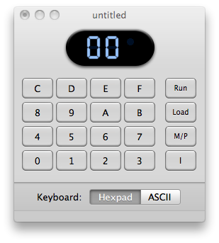
TinyELF Emulator for Macintosh OS X

I’ve now hit chapter 4 in Tom Pittman’s “A Short Course in Programming” book that has been graciously posted online for the world to enjoy.  Chapter 4 deals with registers but almost immediately it sends you back to program 2.3 at the end of chapter 2.  I am going to re-comment the code to attempt to make more sense of it.

.. PROGRAM 2.3 — SLOW BLINK
..
0000    91      GHI   Set D(accumulator) to the to highest byte of register 1
0001    CE     LSZ    Skip the next two bytes if D=0
0002    7A     REQ   This turns the Q bit off if D doesn’t equal 0
0003    38     SKP    This skips the next command when D doesn’t equal 0
0004    7B     SEQ    This turns on Q bit if the long skip jumps past the short skip
0005    11      INC     Increment register 1
0006    30     BR      Jump back to the beginning
0007    00                 This is the target of the 30 command

The reason that the high byte is used because the low byte would equal 0 every 256th time the program loops.  This would cause you to never see the Q bit actually blink on the TinyELF emulator because when you cycle the Q bit that quickly, the emulator thinks you are trying to use the speaker that is also attached to the same line.  So when I set my memory address 0000 to 81 instead of 91, I get a super high pitched dog whistle sound coming from my speakers.

The long skip happens 1/256th of the time.  At the point the Q bit gets set to 1.  The program continues to loop and R1 continues to increment 255 more times but the high byte still equal to 0.  These 256 cycles happen so quickly that you barely get to see the Q bit flash before the high byte in R1 changes to to 01 and the short skip jumps past the 7B command.  The program has to loop 65,280 times before you get to see the Q bit blink briefly.

AHA!

Powered by WordPress. Theme: Motion by 85ideas.