Tag Archive: assembly language


Review: CODE by Charles Petzold

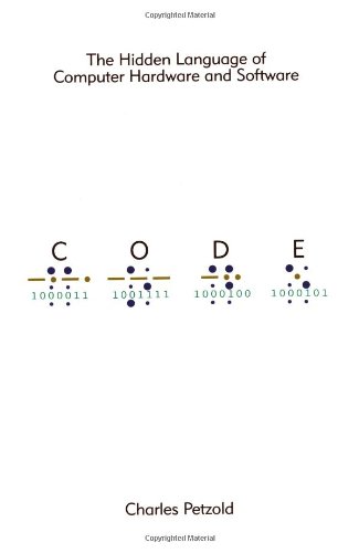
Code: The Hidden Language of Computer Hardware and Software

The cover of CODE does not leave you much to judge it by.  It looks plain and minimalist at best but the reviews on the back cover peaked my interests:

“[A] gem that will appeal to anyone who wants to understand computer technology at it’s essence.”  –David Wall, Amazon.com

” You can tell writing CODE was a labor of love for Perzold and reading it is, too.”  –Bill Camarda, barnesandnoble.com

I agree 100% with both of these reviews of the book but there is much more here.  The author took painstaking care to present topics in a way that makes sense but never dumbs them down into abstracts that are plainly inaccurate like many other books/papers of this nature that overuse poor analogies.  The best way to explain the book is to walk through the chapters a bit:

Chapters 1-6 gently introduce basic principles using a pair of childhood friends who wish to communicate with each other silently after dark when their parents have said “lights out”.  Petzold talks about using a flashlight, morse code and eventually moving up to building a simplistic telegraph system.

Chapters 7-9 builds upon the earlier chapters by explaining different numbering systems and relating them to fingers, toes and bits.

Chapters 10-14 starts to get REALLY interesting where he introduces logic circuits built entirely from telegraph relays.  In earlier chapters, he explains the concepts of telegraph relays and puts them to amazing uses in these chapters.  He brings it as far as building a binary adding machine (conceptually, using your imagination).  As far fetched as it may sound to build a computer entirely from simplistic devices such as relays, it is possible and has been done.  The whole point of this book is to show how simplistic(and simultaneously complex) a computer actually is.

Chapters 15-18 gives an AMAZINGLY gentle introduction to machine code and assembly language which is at the heart of every computer program.  Petzold’s explanation of machine code is by far the best explained version I have seen thus far.  If you want to follow up this book with something useful that will teach you even more about machine language, check out A Short Course In Computer Programming and if you run a Mac, grab the TinyELF 1802 emulator.

Chapters 19-22 work up to slightly higher-leveled details such as handling keyboard input, video output and an interactive console.  The explanations in these chapters are VERY easy to understand.

Chapters 23-25 close out the book with the significance and methods of processing floating point numbers(any number with a decimal point in it).  Higher level languages such as BASIC, C and some others that even I had not heard of.  Finally he closes out the book with the shift into graphical user interfaces, object oriented programming and API’s.  Even if those things sound mind boggling, by the time you read to this point in the book, you will easily be able to grasp these concepts.

Petzold does an amazing job of putting all of the concepts he is trying to convey into a palatable order.  Furthermore, when the reading has gotten REALLY thick in certain chapters, he promptly brings things back into perspective and switches gears into lighter topics like history which gives you a chance to absorb what he has just said and connect the dots.  Petzold also keeps it interesting by referencing later chapters in the book, this is probably one of the reasons that I absolutely could not put this book down.  I managed to plow through it in 3 days.  For anyone interested in computers, this book is a must because it gives you and excellent foundation to learn higher level concepts off of.  Yes, the book was written in 1999 so some of the examples he gives are dated and amusing such as when he quotes system specs of “modern” systems but NOTHING in this book is any less valid today than it was when he wrote it.

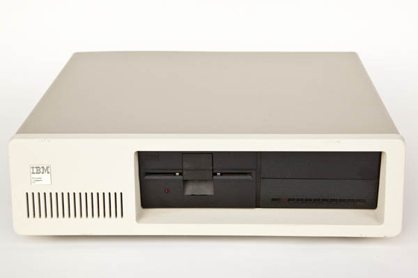
Dusting off my new old IBM PC XT

IBM PC XT front view

I was at a computer recycler the other day and there it was… An original IBM XT 8088 system in nearly mint condition.  It was in the front window of “prized” old crap in this store.  I asked the guy if any of that stuff in the window is for sale and he replied, “sure, sometimes it is”.  So then I specified that I was interested in the XT.  He asked what I’d pay for it and I told him $20.  He said, “sure” and it came home in my trunk.  Luckily on the way out the store I noticed the keyboard sitting there.  I asked him if it was cool if I took it and he said it wasn’t a problem.  Later I found out that it’s a good thing I grabbed it because an AT-style keyboard wouldn’t work.

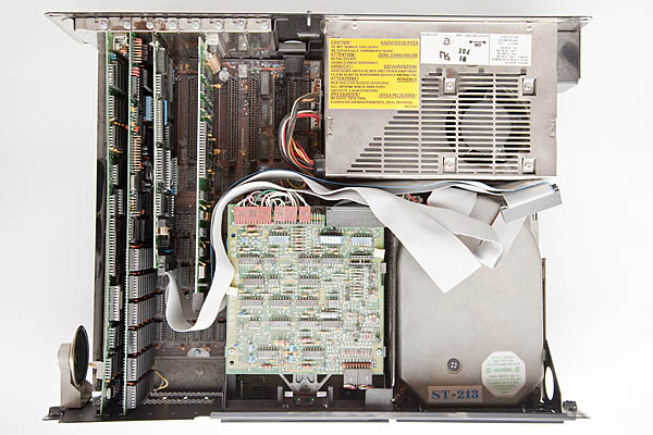
IBM PC XT inside

After bringing it home, brought it out and popped it open to check what was inside.  The system is actually fairly packed.  Someone probably spent $5,000 or so upgrading it to the point it was at.  The memory banks were full and there was an add-on memory card that had a realtime clock as well. Something else I learned was that originally these systems required you to enter the time and date every time you booted them up.  How annoying….  Looking around further, the system has an unmarked graphics card with a printer port.  I would have hoped it was a Hercules but I’m pretty sure it’s not a real one in any event.  There is a 20 megabyte Seagate MFM hard drive and a MFM controller card in there too.  Something else I learned is that IDE pretty much requires a 16-bit data bus to function at all and the 8088 has an 8-bit external bus so it can’t work with IDE without some major trickery so I’m crossing my fingers that the MFM drive still functions.  Lastly, there is a serial port card.

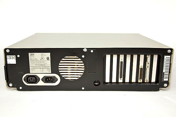
IBM PC XT back

I did plug it in and flip the power on.  Sounds like the hard drive spins up just fine at least.  I’m hoping that it works but I’m currently trying to hunt down an ISA VGA card to test it with.

You may ask why I bothered buying a nearly 30 year old computer.  My original plan was to part it out and build a single board 8088 to learn more about computers but I’ve since changed my mind since this one is in excellent shape.  I have a really cool old book called The 8088 Project Book by Robert Grossblatt.  It goes through the entire process of building up and programming an 8088 based computer on a breadboard.  The picture on the cover is an insane spaghetti mess of wires and breadboards.  Looks like fun but I’m not sure I’m up to the task.

My alternative plan is to use the computer as it sits an attempt to learn some 8088 assembly language in the dos environment.  Might also be fun to try some other operating systems like CP/M or Xenix if I could find copies of them.

TinyELF subtraction

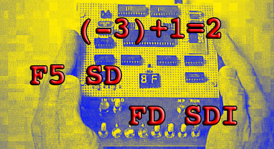
After a long break from Tom Pittman’s online book A Short Course in Programming, I’m digging in again to attempt to understand the second half of chapter 5.  I’m still running the same suggested program which is 5.1 ALU OPS.  The bytecode for subtraction is F5.  There is nothing profound about this command other than you enter the data backwards.  For instance, it’s not:

3-1=2

It’s more like:

(-3)+1=2

If you screw up and go the other way with it, you won’t end up with 2 for an answer, you’ll loop register and come up with FE.  Makes sense to me since 1-3=FE on the 1802 which cannot directly represent signed numbers natively.  So the thing to take away from this is that the “negative” number is the first operand that you will input after the instruction.  The second number will always be interpreted as a positive number.

The next subtraction instruction is FD which tells the 1802 to subtract the next byte in memory after the instruction from whatever is in the memory location 0060.  The third byte of the default, unmodified program is ignored and replaces with C4 since that lives at location 2A in memory.  If I put in FD, 01, 55, the computer does this:

(-01)+C4=C3

This part of the chapter is getting sticky for me again.  Hopefully I’ll be ready to muddle through it some more shortly.

Moving on with chapter 5 of “A Short Course In Programming“, I’m finding some more nifty opcodes to dissect.  These versions are sort of the evil twins of the first three that I went over in part 1.  Key in program 5.1 if you haven’t already.

ORI – The bytecode for ORI is F9.  Let’s bring back the pair we’ve been using all along.  F9, 33, 55:

33 = 0011 0011

55 = 0101 0101

F7 = 1111 0111

Woah!  What’s the deal?  This isn’t what we are used to at all.  Let’s flip this thing backwards and see what happens:

55 = 0101 0101

33 = 0011 0011

D5 = 1101 0101

Hmmm, that didn’t help.  Perhaps a different approach:

FF = 1111 1111

FF = 1111 1111

FF = 1111 1111

Well I suppose that’s a little better.  The brute force learning method isn’t working for this one.  Time to get to the bottom of this…  Ok.  Slowing the computer to single step through gives a bit of a clue to what is really happening here.  The 33 is not being read at all.  It’s entirely being ignored.  When the program runs, you could put anything in for the second value and it won’t change the outcome because C4 is hard coded into the program in location 002A which is the byte immediately following 0029 where our opcode lives.  When we write it out like this, it makes a ton more sense:

33 = 0011 0011

55 = 0101 0101

C4 = 1100 0100

F7 = 1111 0111

AHA!  We are back to a plain old OR.  This time however, instead of taking the input value from the 0061 location, the F9 opcode ignores the SEX 6 instruction and addresses the immediate byte instead.  I’m sure this will come in handy in the future, I just don’t know how yet.

ANI – Ho hum, more of the same funny business here.  Try FA, 33, 55:

33 = 0011 0011

55 = 0101 0101

C4 = 1100 0100

00 = 0000 0000

ANI is AND in disguise but also ignoring the E6 opcode and simply comparing the datum residing in the next byte of memory.

XRI – Do I even need to explain this one?

33 = 0011 0011

55 = 0101 0101

C4 = 1100 0100

F7 = 1111 0111

XRI is XOR in disguise but once again ignoring the second datum, 55.  As a refresher, XOR changes all bits that are different to a 1 and all bits that are the same to a 0.

ADD You probably think ADD is going to be super easy with no gotchas.  You are mostly correct.  There is only one little thing…  To demonstrate this, I’ll change the numbers up a bit.  The bytecode is F4 BTW:

FF = 1111 1111

01 = 0000 0001

00 = 0000 0000

DOH!  We just blew it.  If you have your “1802 State” window in TinyELF open however, you’ll see that the DF bit is now set high.  This means that FF + 01 actually equals 0100.  Let’s take one step back and check out something more palatable:

33 = 0011 0011

55 = 0101 0101

88 = 1000 1000

If you thought we were through chapter 5, think again.  This is only about half way there.  Oddly, we are also half way through the entire book at this point.  It’s been a long journey, don’t quit now.

I got a bit stuck at the end of chapter 4 of Tom Pittman’s book “A Short Course in Programming“.  Some of the concepts of registers become a bit hard to track but I think I have those fairly well figured out.  Now onto a new tougher section; section 5.  One nice thing about this section is the fact there is only one program to enter.  Unfortunately it’s a bit of a monster compared to the previous programs.  It spans almost 50 bytes!  This program is one of the coolest so far though.  It allows you to put in any opcode and then two bytes of data and see what the outcome is.  The inner workings of the program (5.1) aren’t important here.  The important thing to grasp is what all of these logic and arithmetic opcodes are actually doing.  I will attempt to explain what I think the computer is doing as I figure that out myself.

One interesting note is that the 1802 is computing in binary but you are going to enter everything in hex and get all of your results back in hex.  Follow this link if you need help converting between binary, decimal and hex.

OR – The first opcode that Tom refers to is OR.  OR falls into the logic category.  When I plug into the program F1, 33, 55, I get a value back of 77.  Same goes for F1, 55, 33.  So what is the computer actually doing?  55+33 would be 88 so it’s not adding the numbers together, or is it?

It sort of is.  If you break the numbers back out to binary, this is a little easier to follow:

55 = 0101 0101

33 = 0011 0011

77 = 0111 0111

If you look at the table above, you’ll see that OR is saying that if either of the bits is set to 1, then set to a 1.  If both bits are set to 1, it’s still one.  If both bits are 0, then it’s still 0.  It’s comparing the numbers moreso than adding them together.

If you enter F1, 33, 33, you’ll get 33 because the bits are identical in both bytes so nothing will change.

Let’s test the theory on bigger numbers:

A9 = 1010 1001

DE = 1101 1110

Look at the table.  You should easily see the answer if you understand this concept.  The A byte corresponds with the D byte.  There is a 1 for every spot so ORing them together nets a result of F or 1111.  Now looking at the 9 byte and the E byte, there is also a 1 for every bit there so the result is F as well.

AND – The opcode for AND is F2.  If OR made sense to you, AND should be a piece of cake.  Let’s try our example of F2, 33, 55.  The result is a very perplexing 11.  Putting in F2, 55, 33 will net the same result.  Why?  Let’s look at the binary for the answer:

33 = 0011 0011

55 = 0101 0101

11 = 0001 0001

AHA!  The binary bits BOTH have to be set high in the same locations.  5 and 3 only share one common bit that is set high.  That is the 1 bit.  For the bonus round, how do you get a result returned of FF?  It’s pretty easy when you think about it.  FF has ALL bits set high.  AND only returns a high bit if all corresponding bits are set high.  So F2, FF, FF = FF.  There is only one right answer for that question unlike the OR operations.

XOR – This only sounds scary and confusing because XOR (zor or x-or) is not a familiar word in the English language.  The concept is really fairly simple when you look at it in binary.  Once again, let’s pull up our trusty pair 33 & 55.  F3, 33, 55:

33 = 0011 0011

55 = 0101 0101

66 = 0110 0110

HUH?!?  Where did this 66 come from you say?  Look closer.  If one OR the other bit was set to 1, a 1 is returned.  If both bits were set to 1, you get a 0 back.  If both bits were set to 0, you get a 0 back.  Make sense?  Let’s test the theory on some more interesting numbers:

E9 =1110 1001

3A = 0011 1010

D3 = 1101 0011

FF = 1111 1111

00 = 0000 0000

FF = 1111 1111

This concludes part 1 of my post.  In my next post, I will dissect the ORI, ANI & XRI operators.  Should be interesting…

TinyELF direct keypad output

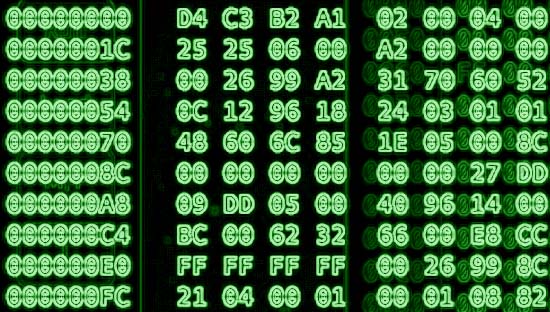
When I first booted the TinyELF before I had ANY clue how to use it, I did what most people would do.  I started punching hex keys in and staring dumbly at the 2 digit display wondering why it didn’t do anything.  Finally, today, I know why.  It’s because it didn’t have this program I wrote up:

0001   6400   OUT4    Clear display

0003   90       GHI        Zero the accumulator

0004   B6       PHI       Set R6 hi to 00

0005   F820   LDI       set accumulator to 20

0007   A6       PLO       Set R6 lo to 20

0008   E6       SEX 6   Point input and output at location 0020

0009   6C      INP C     Read keypad and store at 0020

000A   64      OUT 4    Read 0020 print to display

000B   3002  BR          Loop back

Simple program but it proves a point.  All these years you have expected to push a key, button, knob, whatever and get some sort of feedback, right?  Well that only happens because someone along the way made it so.  In fact Apple has teams of engineers that specialize in nothing but that sort of thing.

Take another look at the computer you are using right now and consider how many lines of code are running behind the scenes that represent seemingly tiny and minute details of how your system behaves.  It’s mind boggling and testament to team work at it’s finest.

TinyELF delay timer

Even this slow old architecture is actually still really quick.  You’ll often need to burn off some clock cycles between operations just so you can see the output.  Here is a little subroutine I wrote for the 1802 that is adjustable and can be shoehorned into code you may have already written.  You can hook it write into many of the early programs in Tom Pittman’s book “A Short Course in Programming“.  Pretty much anything that has you pushing the “I” key for it to move forward.

0020    F81F    LDI The second byte determines the delay amount

0022    B4        PHI R4 Puts the delay counter into R4

0023    32XX   BZ XX Branch if D=0, second byte directs back.

0025    94        GHI R4 Puts the counter from R4 into D for comparison

0026    24        DEC R4 Decrements R4 by one

0027    3020   BR XX Branches back to check if D is zero.

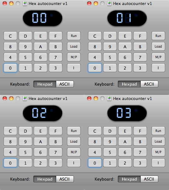
Here is an example where I have hooked the delay back into my hex counter program so that you don’t have to push “I” for the counter to increment.  I have left the old code structure in tact so you can see the differences.  I also changed the counter location in memory to 0030 but this is arbitrary.

TinyELF Hex autocounter

0000   6400  OUT 4    clear hex display
0002   90       GHI R0  zero the accumulator
0003   B2       PHI R2   Set hi byte to zero
0004   B3       PHI R3   Set hi byte to zero
0005   A3       PLO R3  Set lo byte to zero
0006   F830  LDI         Set D to 30
0008   A2      PLO R2  Set R2 to 30
0009 52         STR Clear 0030 byte
000A   E2      SEX R2  Set X to R2
000B   3020 BR           Instead of waiting for “I”, branch to delay
000D   13       INC R3  Count up
000E   83      GLO R3  Set D to the current count
000F   52       STR R2   Store counter value in 0030
0010   64        OUT 4     Put contents of 0030 on display
0011   22        DEC R2  Keep X pointing at 0030
0012   C4C4   NOP        No need to wait for “i” to be lifted now
0014   300B   BR           Loop back to where wait for “I” was

timer routine;
0020   F85F LDI         The second byte determines the delay amount
0022   B4      PHI R4  Puts the delay counter into R4
0023   320D BZ          Branch when D=0 back to AFTER the branch to 0020
0024   94      GHI R4  Puts the counter from R4 into D for comparison
0025   24      DEC R4  Decrements R4 by one
0027   3023 BR           Branches back to check if D is zero.

TinyELF Hex Counter

I’ve been trying to figure out how to do this nearly since the beginning.  This program represents a huge milestone for me.  It’s the first program that I have created from scratch that does something sort of useful.

It’s amazing how much debugging can go into something so simple as a hex counter.  At first I had to press “I” three times for the counter to start moving upward.  Turns out I had a few commands out of order.  Also, I had a bug where the counter location in memory would not have been properly reset to zero if R2 didn’t have a residual value in it.  Then I had some other misplaced bytes that were confusing me a bit.  I think I have all the kinks worked out now so I’d like to present my hex counter:

0000     6400    OUT    4        clear hex display
0002     90         GHI     R0    zero the accumulator
0003     B2         PHI    R2      Set hi byte to zero
0004     B3         PHI    R3      Set hi byte to zero
0005     A3         PLO    R3     Set lo byte to zero
0006     F820    LDI                Set D to 20
0008     A2        PLO    R2      Set R2 to 20    
0009     52        STR           Clear 0020 byte
000A     E2        SEX    R2      Set X to R2
000B     3F0B   BN4               Wait for “I” to be pushed
000D     13         INC    R3      Count up
000E     83        GLO    R3      Set D to the current count
000F     52         STR    R2      Store counter value in 0020
0010      64        OUT    4         Put contents of 0020 on display
0011      22         DEC  R2        Keep X pointing at 0020
0012     3712     B4                   Wait for “I” to be lifted
0014     300B    BR                  Loop back to wait for “I”

Please excuse the formatting, it’s late.  Anyhow, the program sets itself up by clearing the display, zeroing R3, setting R2 to 20, clearing the byte at memory location 20 and of course setting X to R2.  R2 does double duty in this program.  It points X at byte 0020 in memory and it also tells the STR instruction where to store the value of D.

After the initial setup, we jump into the loop.  First we increment R3(the counter).  Next we stick the counter value in D so we can then store D at memory location 0020.  Then we display the value of 0020 since that is where R2 is pointing.  The 64 OUT 4 instruction incremented the value in R2 so we decrement it immediately so R2 still points at the correct location and doesn’t leak memory.  If you want a good demo of a memory leak, change the value of 0011 from 22 to C4 and then run the program.

I know this program isn’t rocket science but give me a break, I’m still in chapter 4.  Looks like I still have a LONG ways to go to program in “hello world” even…

In Tom Pittman’s book, “A Short Course in Programming“, he introduced the 64 OUT4 instruction in chapter 3 with little explanation other than saying that OUT 4 would output the next byte in memory to the hex display.  This is fine and dandy of course but only if P=X.  I glossed over the P=X part the first time I read chapter 3 however so when he re-introduced OUT 4 in chapter 4, I found myself a bit confused.  In program 4.2, he tries to make sense of this concept.  I am going to take the liberty of recommenting the code to try to make even more sense of it and drive this concept home:

0000 90		GHI 0	.. set D=R0(hi byte), R0=0 after the computer resets
0001 B8		PHI 8      set high byte of R8 to value of D which is zero
0002 80		GLO 0      set D=R0(lo byte), this could JUST as easily be 90
0003 A8		PLO 8      set low byte of R8 to value of D (again, zero)
0004 3F04 WOW:	BN4 *	.. WAIT FOR "I" (This is a good description)
0006 E8		SEX 8      set X register to point at R8
0007 64		OUT 4	.. OUTPUT TO DISPLAY (see more down below)
0008 C4		NOP	.. this byte gets ran so it is critical
0009 3709	B4 *       wait for you to take your finger off "I"
000B 3004	BR WOW	.. REPEAT (start at the wait for "I" statement)

This program as written sends every byte in memory out to the hex display starting at location 0003 in memory.  If you want to start at the beginning of the memory, change 0002 to 90.  This will make sure that R8 is completely zero’d out when you start your count.  One more observation I have is that location 0008 DOES get executed.  If you want to make a slightly more confusing program but save a byte of memory, you can omit the c4 instruction at the location.  Just make sure you change the next branch command to 3708 so it jumps to the correct location.  You can FURTHER save another byte of memory if you omit the 80 GLO command.  Once you’ve GHI’d, you have your D(accumulator) set to zero so why not just PHI and PLO after that without GLOing?

Now for the big explanation.  Obviously the meat of the program happens when X gets pointed at R8.  That tells the OUT4 instruction to output whatever memory location that R8 is pointing at to the hex display.  Usually OUT4 looks at R0 for it’s next byte to display.  It also increments whichever register it’s looking at.  This is why the next byte after 64 usually is skipped and not executed.  Hopefully this makes perfect sense to you by now.  Also, there is nothing special about R8.  Tom just arbitrarily chose R8 out of the stack.  Here is my modified version of Program 4.2 that is smaller, starts at an earlier memory location and uses R2 as the display byte pointer(if that is the proper term…):

0000 90		GHI 0	.. set D=R0(hi byte), R0=0 after the computer resets
0001 B2		PHI 8      set high byte of R2 to value of D which is zero
0002 A2		PLO 8      set low byte of R2 to value of D (again, zero)
0003 3F03 WOW:	BN4 *	.. WAIT FOR "I" (This is a good description)
0005 E2		SEX 8      set X register to point at R2
0006 64		OUT 4	.. display contents of memory location pointed to by X
0007 3707	B4 *       wait for you to take your finger off "I"
000B 3003	BR WOW	.. REPEAT (start at the wait for "I" statement)

In trying to understand the PLO (put low bit in D) and the GLO (get low bit from D) commands, I’m going to write a program that cycles through R1-RF and increments the registers one at a time.  This program is pretty darned boring unless you have the memory contents in full view on the emulator.  Let’s get started:

0000      90      GLO         Set D to zero

0001       A1      PLO         Set R1 to zero

0002      11       INC          Increment R1 (This is the start of where we loop it)

0003      91      GLO         Set D to value of R1

0004      A2     PLO         Set R2 to value of D

0005      92     GLO         Set D to value of R2

0006      A3     PLO         Set R3 to value of D

0007      93     GLO         Set D to value of R3

……      and so on and so on until  …….

0020     30      BR            Unconditional branch to the next byte

0021      02                       Start the program again from 0002

I would suggest running this program in step mode.  This program was designed to HAMMER DOWN the function of these two commands for me.  It’s very illustrative of what these commands do if not a bit repetitive.

I’m starting to wonder how I can write a byte to a specific location in memory now.  Specifically right after a 64 OUT 4 command.  It would be nice to get some of the output devices involved in the fun here.  I have some ideas of how it might work but I’m sweating with anticipation.

Another AHA moment!  The BR 30 (Branch Unconditionally) command is simply changing the value of whatever register that P is pointing at.  The value of P can be changed by the Dr SEP (Set P) command.  It’s starting to all make a bit more sense.  (Pun intended)

Powered by WordPress. Theme: Motion by 85ideas.